Network Management
Introduction
By default, all virtual machines are attached to the OpenShift software-defined network (SDN), which enables access from other workloads on the OpenShift cluster, including other VMs and any OpenShift native applications.
-
The SDN provides additional features for abstracting, connecting, and exposing applications in a controlled manner, whether deployed as VMs or Pods in the cluster. These include the Service and Route features of OpenShift.
-
OpenShift’s network policy engine allows the VM user or administrator to create rules which allow or deny network traffic to and from individual VMs or entire projects/namespaces.
However, virtual machines may also connect directly to one or more external networks, such as VLANs, when needed. This is in addition to the SDN, which means that, for example, the administrator can connect to the VM from an external IP address, but the application communicates across the SDN with other VMs hosted by OpenShift Virtualization.
At a high level, this is done by configuring the host networking, by creating a NodeNetworkConfigurationPolicy such as creating a mode 4 (LACP) bond and a OVS bridge on top. With this networking infrastructure set up, we can define NetworkAttachmentDefinitions to allow VMs to connect to that bridge, and therefore, directly to the external network. The next section in this lab will cover those steps.
| The OpenShift environment has already been configured with an OVS Bridge on each compute node your virtual machines will connect to, thus allowing for easy connectivity with/from outside network resources. |
-
Create a network attachment definition
-
Connect a VM to the external network
Create a Network Attachment Definition
In order to use the OVS Bridge with your VM you need to create a Network Attachment Definition. This is what tells OpenShift about the network and allows the virtual machines to connect to it. Network Attachment Definitions are specific to the project/namespace they’re created in, unless they’re created in the default project. This gives you, the administrator, the ability to control which networks are and aren’t available to users who have access to manage their own VMs. Once the Network Attachment Definition has been created, it can then be used by virtual machines when configuring their network adapters.
| A network attachment definition instructs openshift to utilise an existing network device. In our case that device was previously created and is named ovs-br. You must use that name or OpenShift won’t be able to place your VM on any compute nodes as it can only utilise nodes with that specifically named network device on it. |
How is this done?
To manage an OpenShift node’s network configuration you use a tool, available as an operator, called nmstate. With nmstate you can create network interfaces on OpenShift compute nodes using Kubernetes constructs or the NodeNetworkConfigurationPolicy wizard available in the OpenShift console. You can create devices and customize those so that they follow the naming conventions that suit your needs, and your network requirements. For more info about nmstate, and to learn more about the host networking and how to view and manage the configuration, see the documentation here.
-
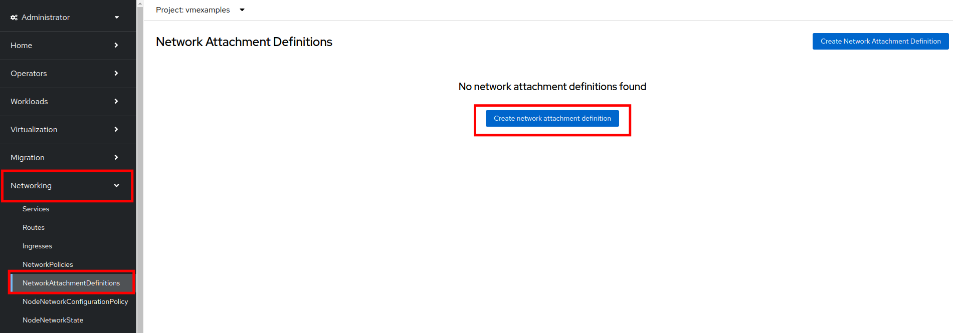
Navigate to Networking → Network Attachment Definitions and click Create network attachment definition:
-
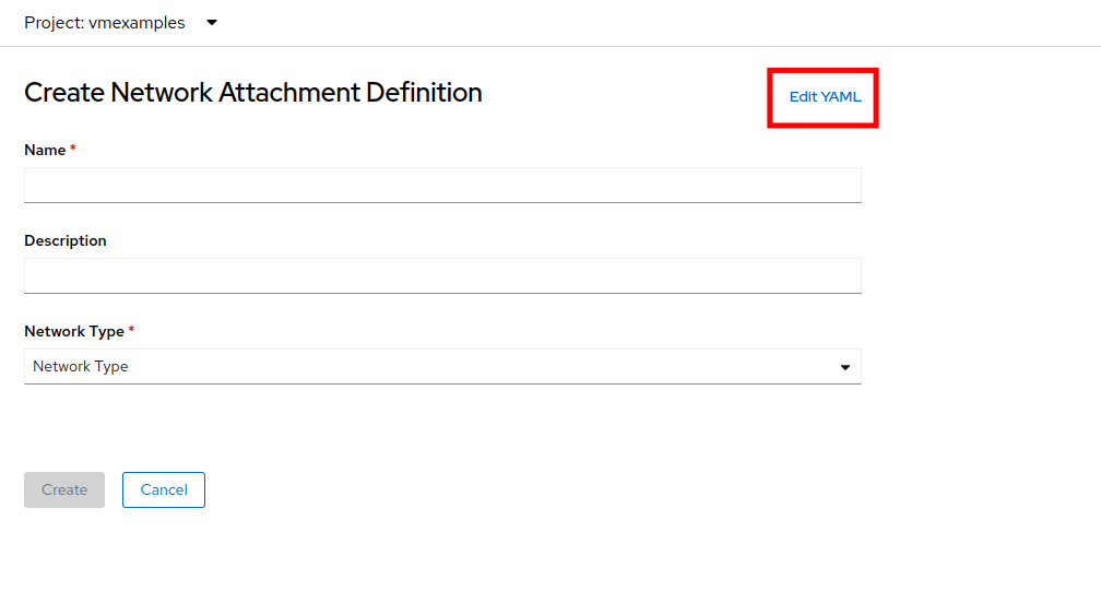
Click the Edit YAML button at the top of the page.
-
Paste in the following yaml snippet, and click the Create button:
apiVersion: k8s.cni.cncf.io/v1
kind: NetworkAttachmentDefinition
metadata:
  annotations:
    description: l2 connection for vms
  name: vlan0
  namespace: vmexamples
spec:
  config: |-
    {
      "cniVersion": "0.4.0",
      "name": "vm-network",
      "type": "ovn-k8s-cni-overlay",
      "topology": "localnet",
      "netAttachDefName": "vmexamples/vlan0"
    }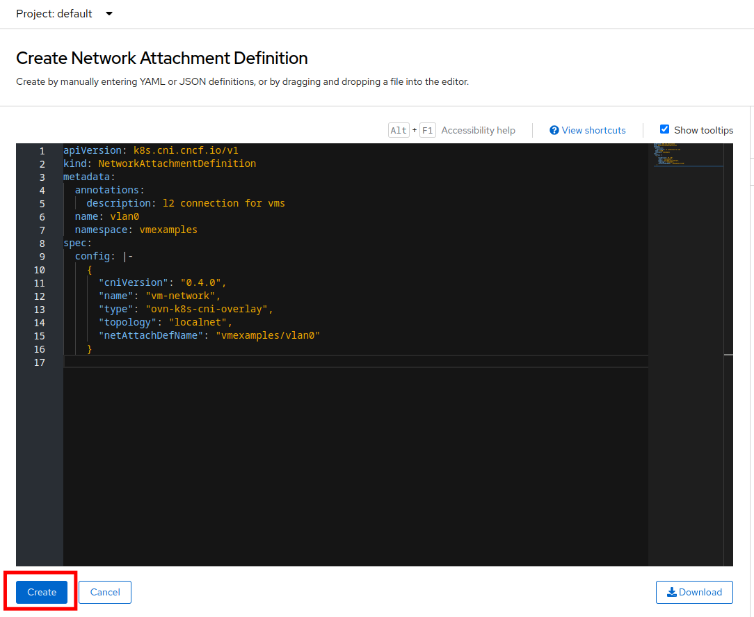
In most cases a single OVS bridge can support many Network Attachment Definitions each with their own designated VLAN Tag Number. In this lab we use an untagged network, so no VLAN number is required here, as such our Network Attachment Definition is labeled as vlan0. -
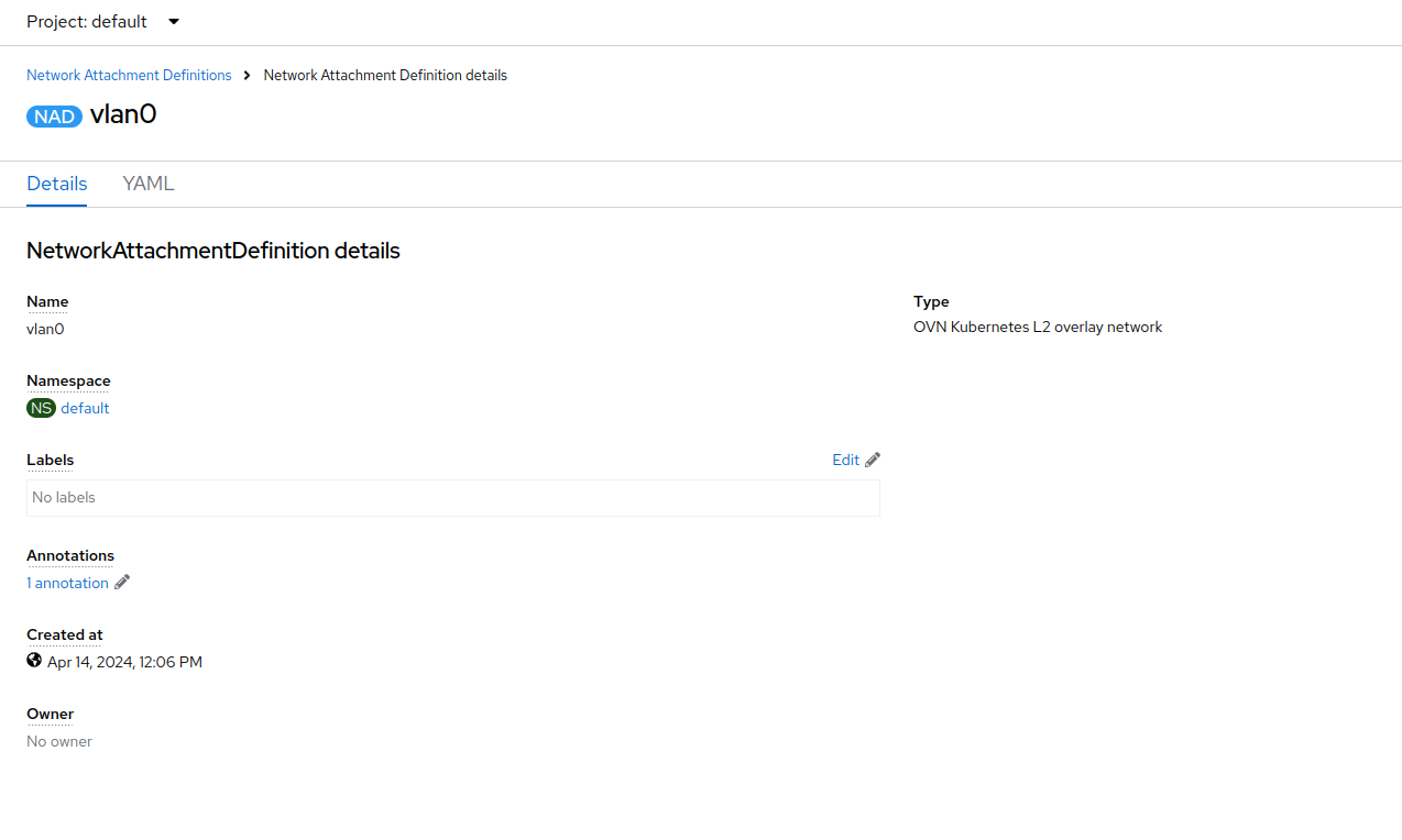
Examine the details of the network attachment definition. Because this was created in the vmexamples project, it will be available only to attach to VMs that are in that project.
Connect a Virtual Machine to an External Network
-
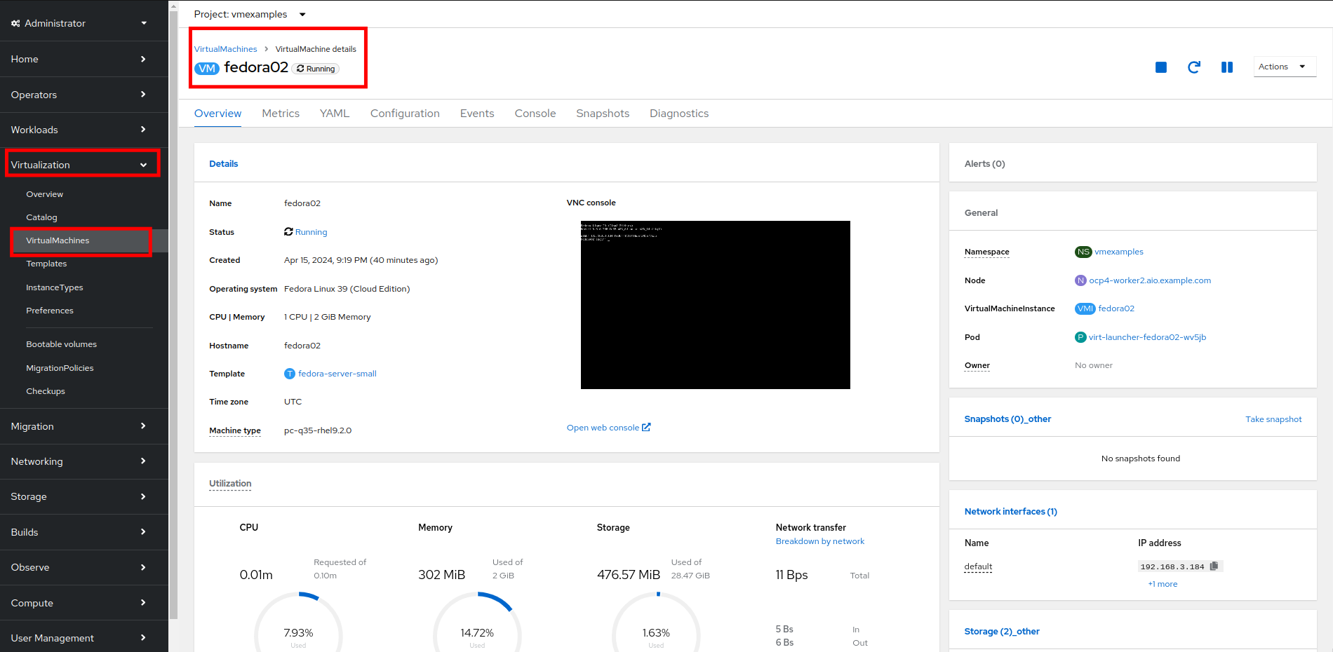
Navigate to Virtualization → VirtualMachines, select the fedora01 VM. Click Configuration tab and then click the Network subtab:
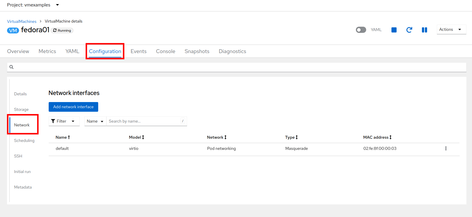
Notice that the VM is currently using a single interface default which is connected to the Pod networking network. We can choose to modify this existing connection or add a new interface to the VM. Either action we choose currently requires a VM restart. -
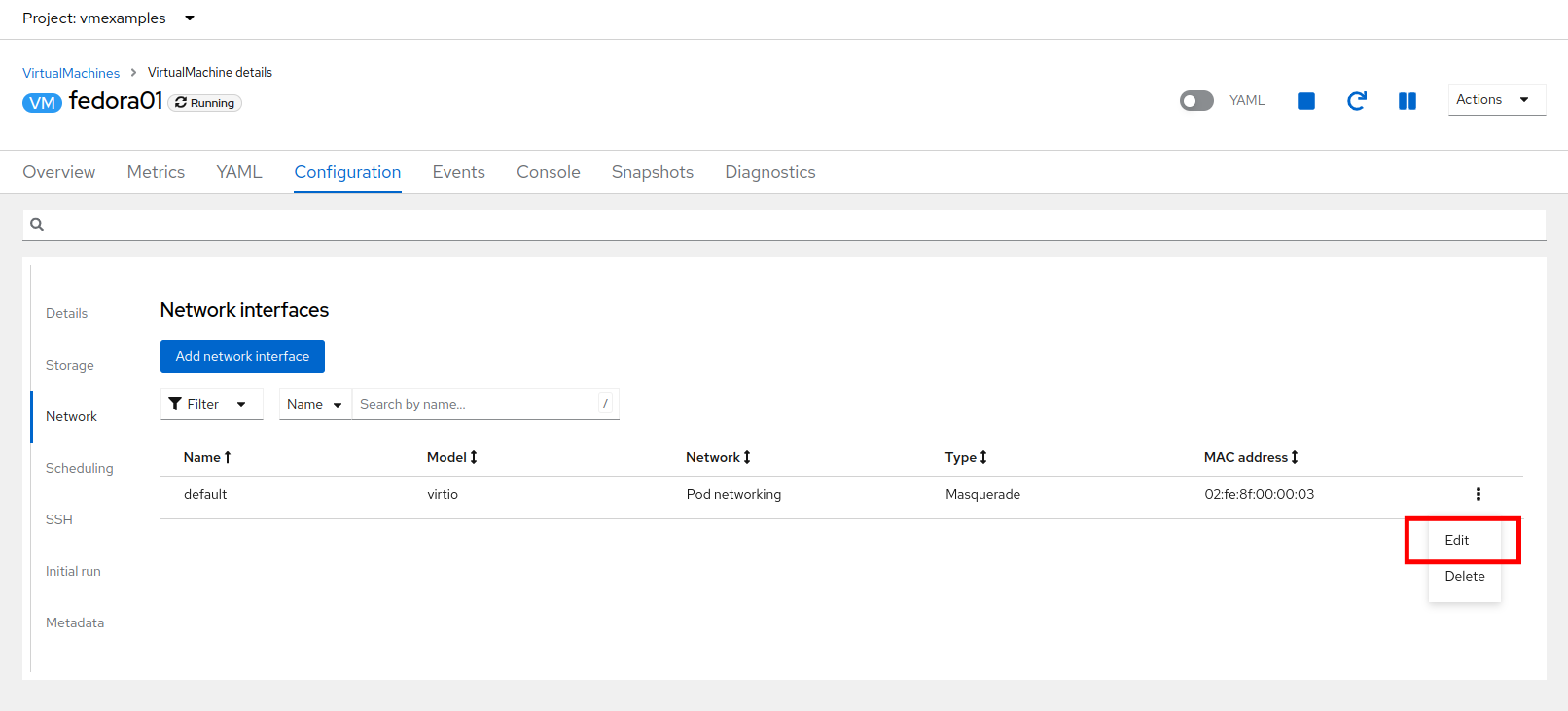
Click the three-dot menu at the end of the default network adapter line, and click on edit in the drop down menu.
-
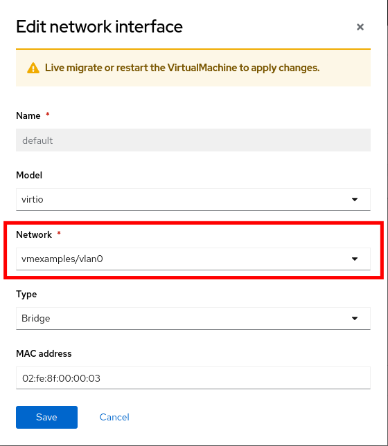
Click the dropdown menu for the Network field, and select the vmexamples/vlan0 network attachment definition that we created. Click on Save.
-
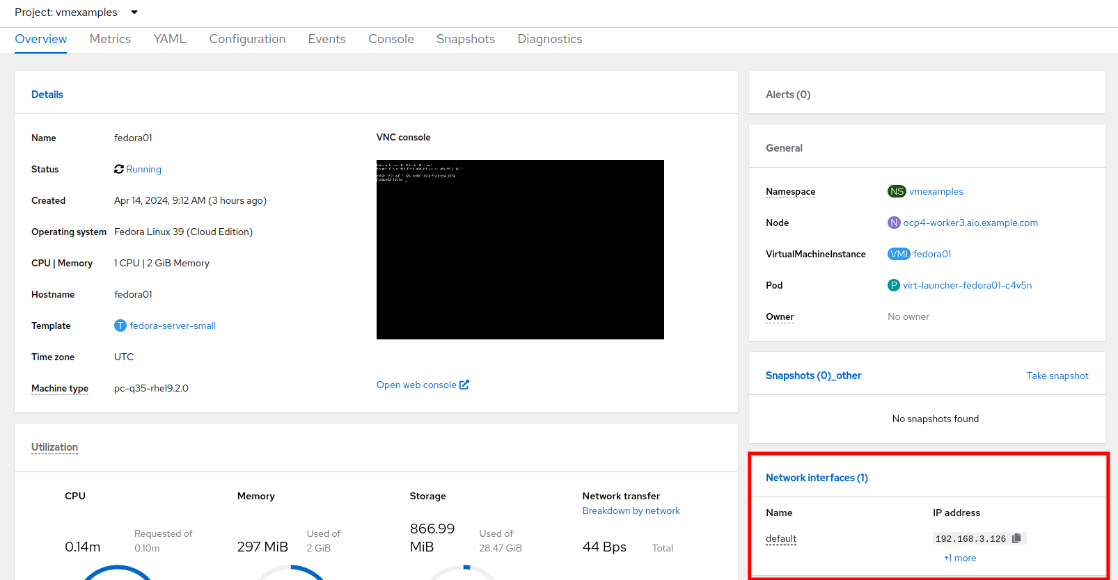
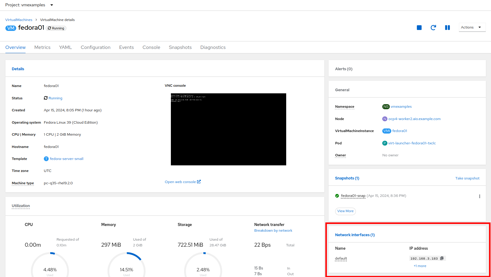
Use the Actions menu or icon in the upper right corner to restart the VM. After rebooting, navigate to the Overview tab:
-
Once the machine restarts, you can see in the Network Interfaces section of the Overview screen that the default interface obtains a DHCP IP address from the flat network (192.168.3.x/24).
| Before the next section of this lab, please repeat the actions to attach the fedora02 VM to the same vlan0 network. |
Using a MultiNetwork Policy
A multinetwork policy allows you to configure network access to a namespace and to define granular rules allowing ingress and egress from the namespace to enhance security of the applications and VMs that are running in the namespace.
| This section of the lab is primarily performed through the CLI. You will need to ssh to your Bastion host where the CLI tools are already installed. Use the SSH Terminal on the right to connect to your bastion host sudo ssh root@192.168.123.100 |
Create a MultiNetwork Policy
For this section of the lab we are going to create a MultiNetwork Policy that prevents all network traffic from reaching the VM’s that are attached to our vmexamples/vlan0 Network Attachment Definition including our VMs fedora01, and fedora02. We will then explicitly allow one-way connectivity from fedora02 to fedora01 to show how we can find tune network connections, even within the same namespace.
| The IP addresses of your virtual guests may differ from those in the attached images or examples, verify the correct addresses present in your lab environment by clicking on the Overview screen for each VM and taking a look at the Network interfaces tile. |
-
From our bastion host we want to paste the following content into a new file called deny-all.yaml:
apiVersion: k8s.cni.cncf.io/v1beta1 kind: MultiNetworkPolicy metadata: name: deny-by-default annotations: k8s.v1.cni.cncf.io/policy-for: vmexamples/vlan0 spec: podSelector: {} policyTypes: - Ingress ingress: [] -
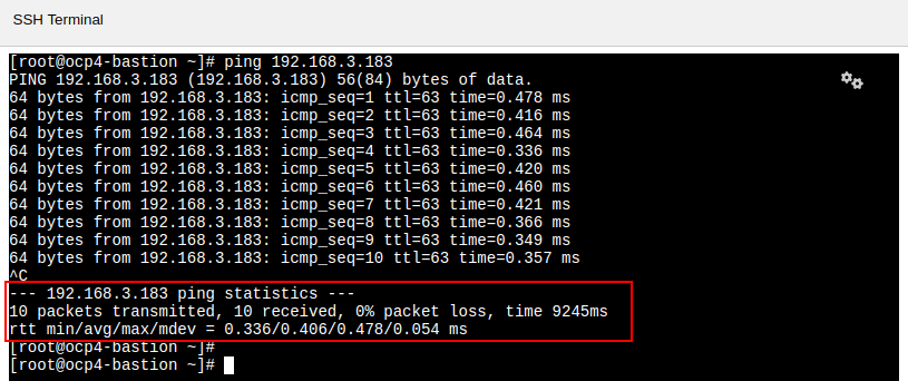
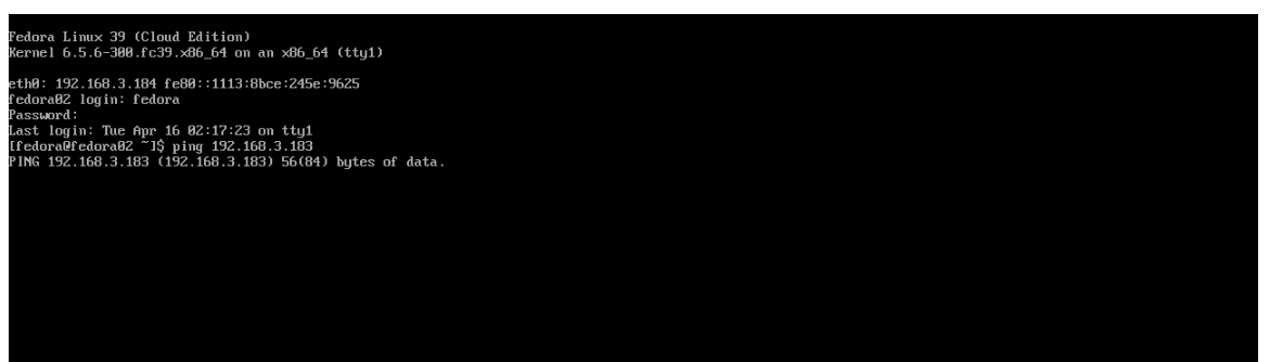
Once the file is saved, start a ping to the IP address of the fedora01 virtual machine to confirm that you can currently connect.
-
Apply the multinetwork policy with the following syntax:
oc apply -f deny-all.yaml -n vmexamples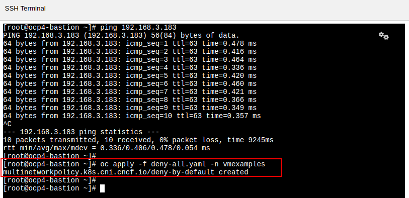
-
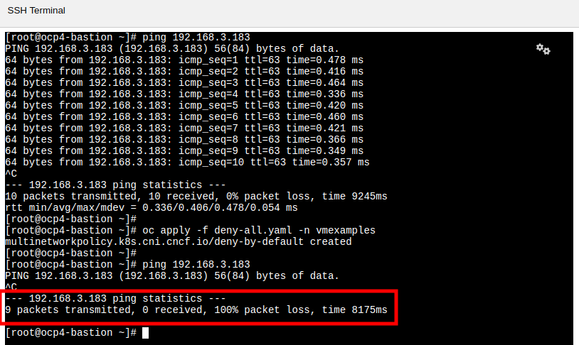
Now try again to ping the IP address of the fedora01 virtual machine, your ping attempts should now fail.
-
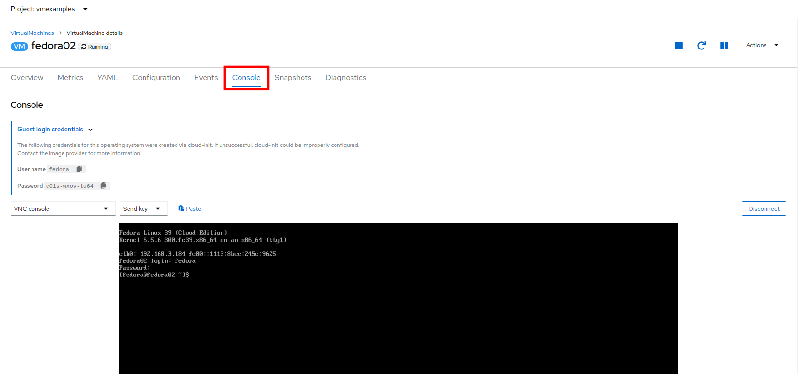
Return to your OpenShift console, and click on Virtualization → VirtualMachines and select your fedora02 machine.
-
Click on the button to open it’s web console, and login with the provided credentials.
-
Attempt to ping the ip address for the fedora01 virtual machine, notice that it is also blocked, even though we are on the same subnet, in the same namespace. Leave the ping running.
-
Return to the bastion host console, and create a new file called allow-host.yaml, and paste in the following content:
apiVersion: k8s.cni.cncf.io/v1beta1
kind: MultiNetworkPolicy
metadata:
  name:  ingress-ipblock
  annotations:
    k8s.v1.cni.cncf.io/policy-for: vmexamples/vlan0
spec:
  podSelector: {}
  policyTypes:
  - Ingress
  ingress:
  - from:
    - ipBlock:
        cidr: <IP_ADDR_FROM_FEDORA02>/32
Make sure that you substitute the correct IP from the Fedora02 VM. 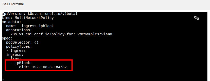
-
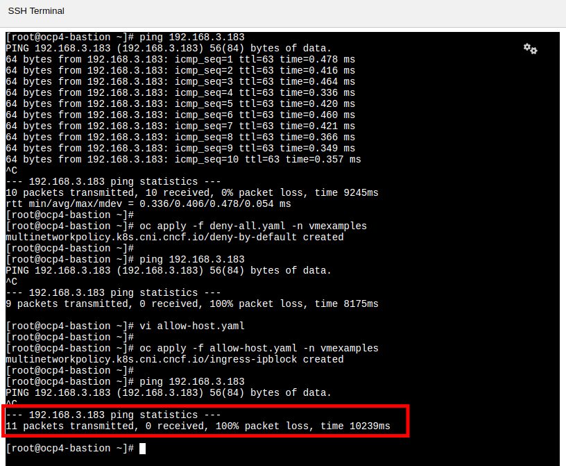
Apply the policy using the following syntax:
oc apply -f allow-host.yaml -n vmexamples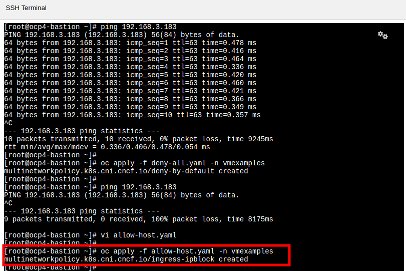
-
Attempt to ping from the bastion host. This attempt should still fail as we have not explictly allowed it.
-
Return to your fedora02 VM console, you should find that the ping has now resumed successfully.

-
Let’s clean up the policies for the next section.
For the next lab, it’s important that we clear out the two network policies we created. Please run the following two commands:
oc delete -f allow-host.yaml -f deny-all.yaml -n vmexamples
Summary
In this section we learned a little bit more about how networking works in OpenShift Virtualization. We created a network attachment definition so that our VMs have network access from outside of the cluster. We also implemented a MultiNetwork Policy to demonstrate how we can secure connections to our VMs by only allowing specified hosts access.