Network Management for Virtual Machines
Introduction
As mentioned in the previous section, all virtual machines are attached to the OpenShift software-defined network (SDN) by default, which enables access from other workloads on the OpenShift cluster, including other VMs and any OpenShift native applications, and for the virtual machines and the applications they host to be managed in a more modernized workflow.
-
The SDN provides additional features for abstracting, connecting, and exposing applications in a controlled manner, whether deployed as VMs or Pods in the cluster. These include the Service and Route features of OpenShift.
-
OpenShift’s network policy engine allows the VM user or administrator to create rules which allow or deny network traffic to and from individual VMs or entire projects/namespaces.
However, it is also possible for virtual machines to connect directly to one or more physical networks, such as untagged network or VLANs, when needed. This is in addition to the SDN, which means that, for example, the administrator can connect to the VM from an external IP address and VMs can connect directly using a Layer2 network.
At a high level, this is done by configuring the host networking, such as a Linux bridge. This workshop segment will walk through the next step in that process, creating a network attachment definition to allow VMs to connect to that bridge and, therefore, directly to the physical network.
| The OpenShift environment has already been configured with a Linux Bridge on each compute node your virtual machines will connect to, thus allowing for easy connectivity with/from outside network resources. |
Review environment
The Kubernetes NMState Operator provides a Kubernetes API for performing state-driven network configuration across the OpenShift Container Platform cluster’s nodes with NMState. The Kubernetes NMState Operator provides users with functionality to configure various network interface types, DNS, and routing on cluster nodes. Additionally, the daemons on the cluster nodes periodically report on the state of each node’s network interfaces to the API server.
-
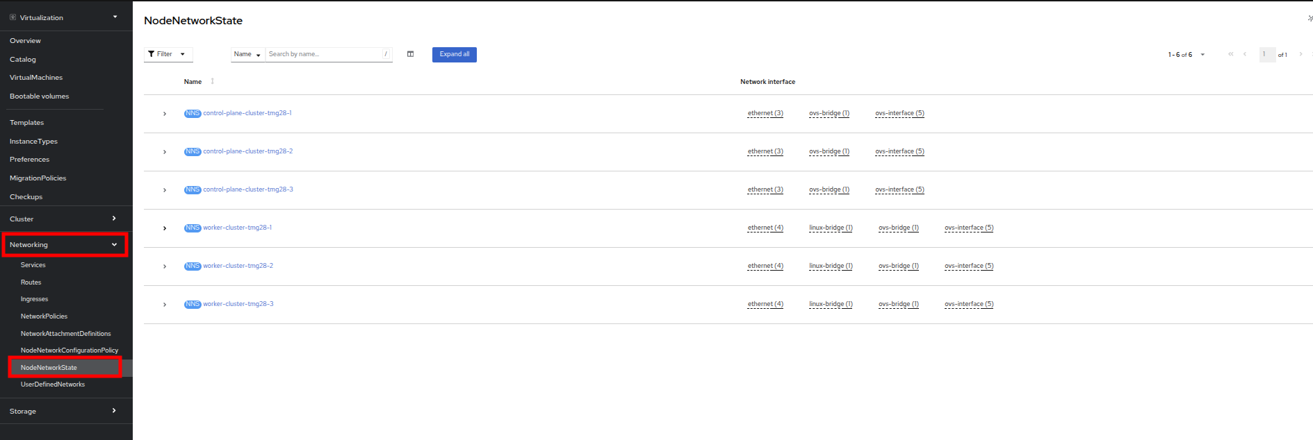
In the left-side menu, click on Networking and then NodeNetworkState to review the current configuration.
-
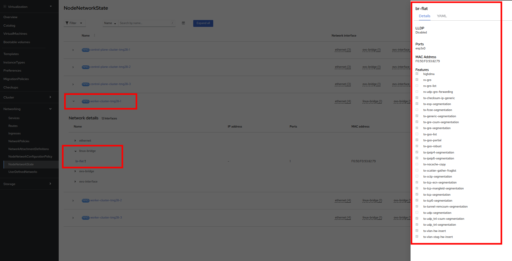
As stated, you will notice that the worker nodes have a linux bridge already configured to be used for this module. Expand one of the workers and click on the bridge br-flat to gather more information about it.
-
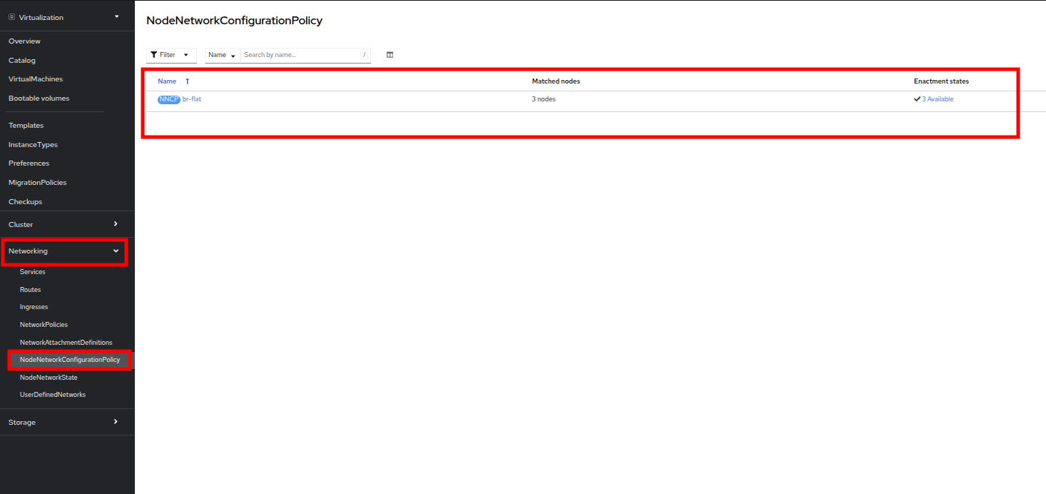
Close the bridge details by clicking on the X in the corner. This bridge named br-flat was created using the Kubernetes NMState Operator. Click on NodeNetworkConfigurationPolicy in the left-side menu to explore more.
-
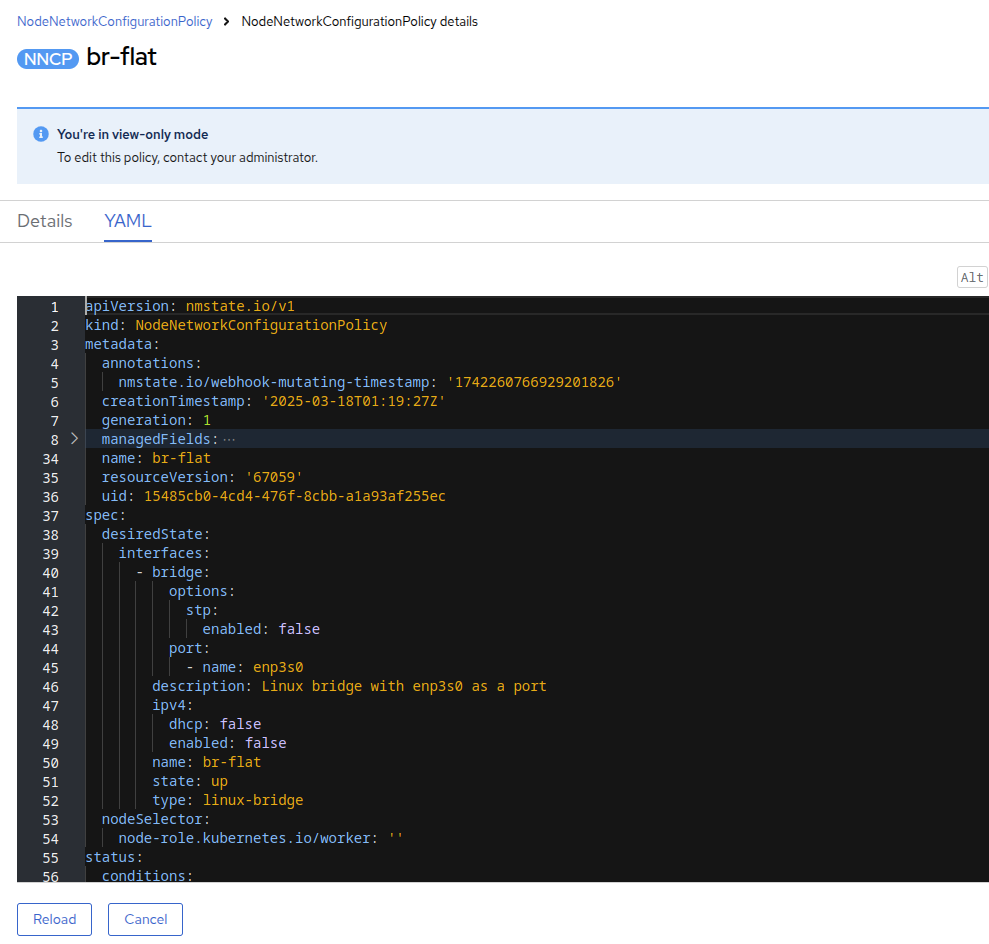
Select br-flat to get information
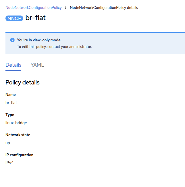
| As the NodeNetworkConfigurationPolicy performs configurations at the node-level you cannot modify these options with your current user account. As a result, it prompts you to contact your administrator. |
-
To see how this bridge was created, you can switch to YAML to see the definition. As an administrator, you could create your a similar bridge with the yaml snippet below.:
Create Network Attachment Definition
In order to use the Linux Bridge with your VM you need to create a Network Attachment Definition. This is what tells OpenShift about the network and allows the virtual machines to connect to it. Network Attachment Definitions are project scoped, to the project that they are created in and are only accessible to the virtual machines that are deployed in that project. If a Network Attachment Definition is created in the default project, then it becomes available globally. This gives you, the administrator, the ability to control which networks are and aren’t available to specific users who have access to manage their own VMs.
| A network attachment definition instructs Openshift to utilise an existing network device. In our case that device was previously created and is named br-flat. You must use that name or OpenShift won’t be able to place your VM on any compute nodes as it can only utilise nodes with that specifically named network device on it. |
-
From the left-side menu, select Network followed by Network Attachment Definitions and click the Create network attachment definition button.
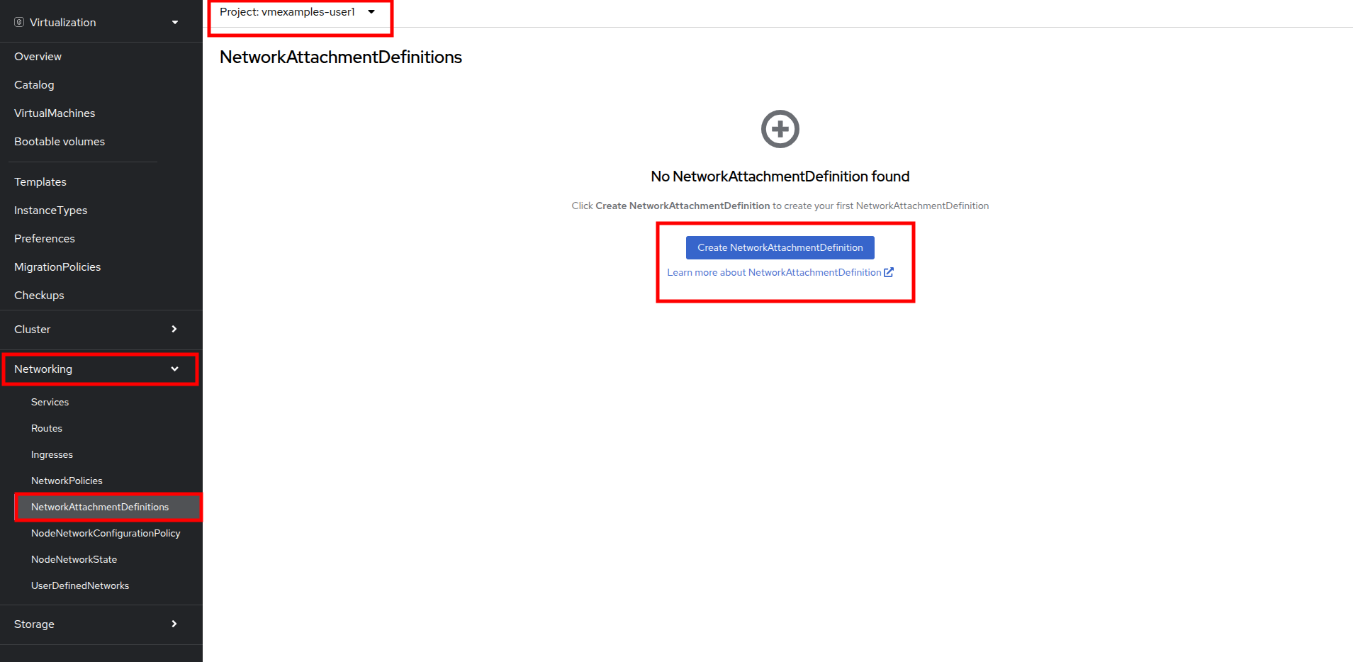
Ensure that you are in your vmexamples-{user} project when creating the network attachment definitions. -
Complete the form for the vmexamples-{user} project as follows, then click Create network attachment definition:
-
Name: flatnetwork
-
Network Type: Linux bridge
-
Bridge Name: br-flat
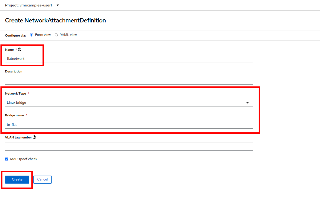
The form above has an input for VLAN Tag Number, which is used when connecting to a network that needs to have a VLAN tag assigned. This lab uses an untagged network, so no VLAN number is required here. A single Linux bridge on the host can have many different VLANs associated with it. In this scenario, you only need to create a Network Attachment Definition for each one, not a separate host interface and bridge.
-
-
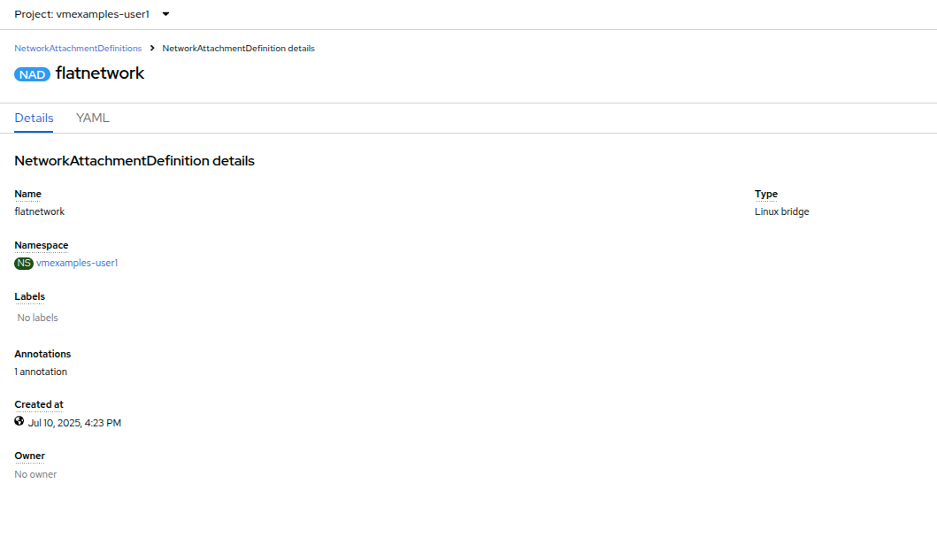
Examine the details of the network attachment definition. Because this was created in the vmexamples-{user} project, it will not be available in other projects.
Attach Virtual Machine to Network
-
Navigate to VirtualMachines in the left-side menu and select the fedora01 VM from the central column. Click Configuration tab and then click the Network left tab:
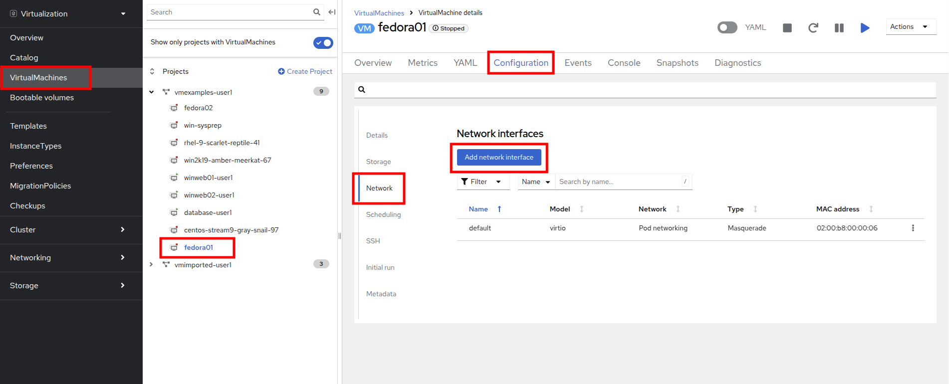
-
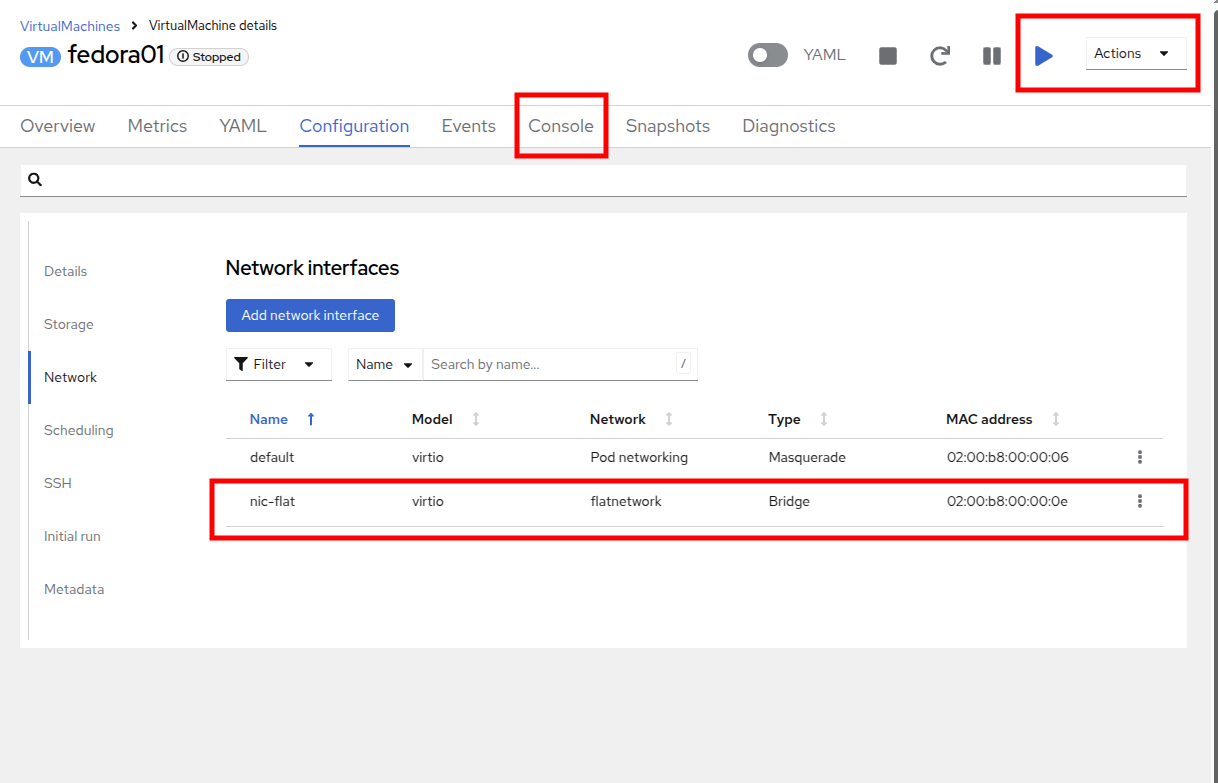
Click Add Network Interface, complete the form as shown, then click Save.
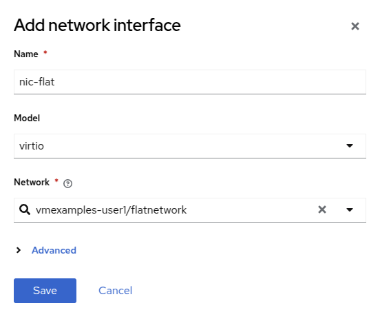
Because this is a bridge connecting to the external network, we don’t need to rely on any OpenShift features or capabilities to enable access, such as masquerade (NAT) for the virtual machines using the network. As a result, type should be Bridge here. -
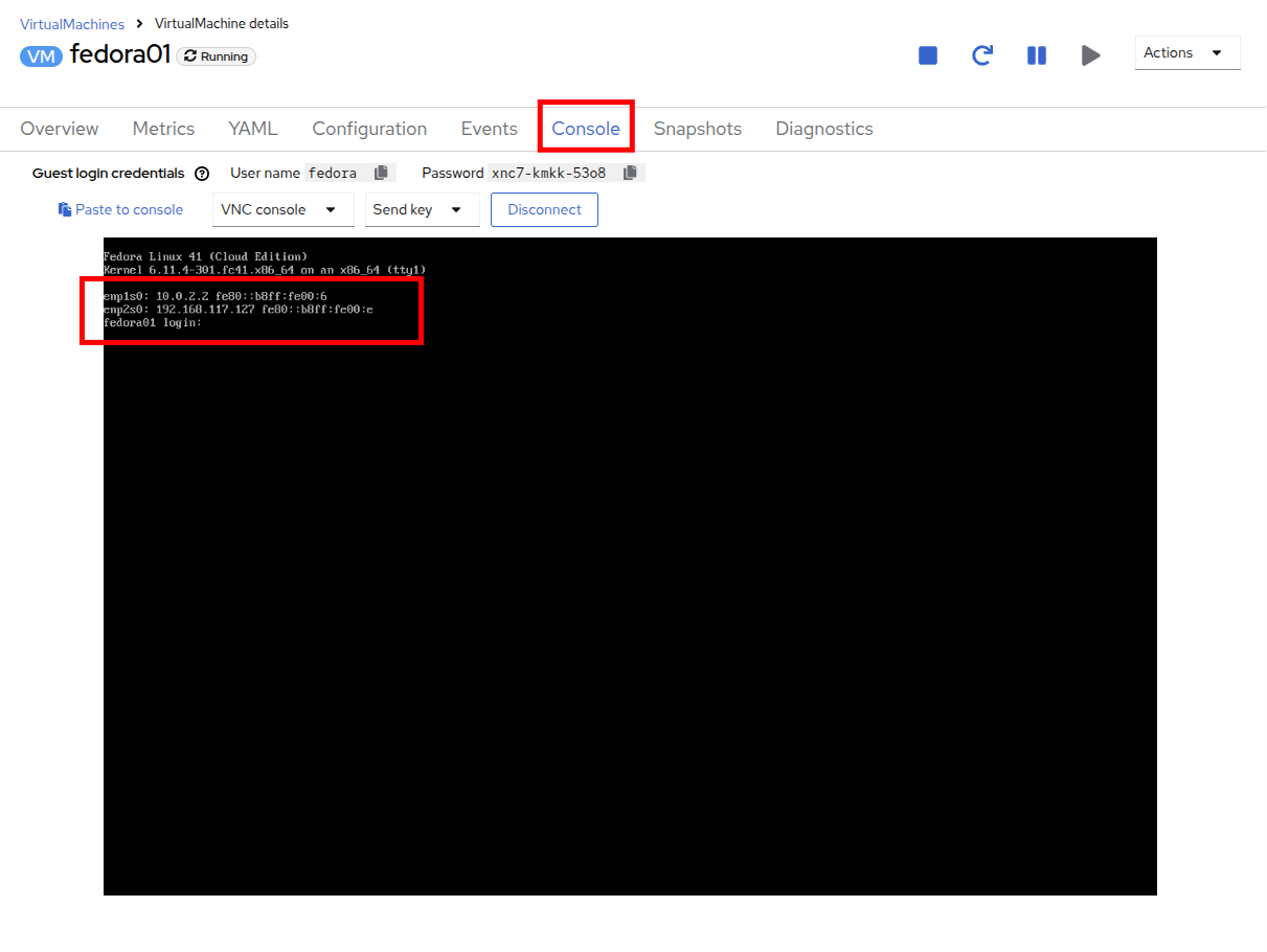
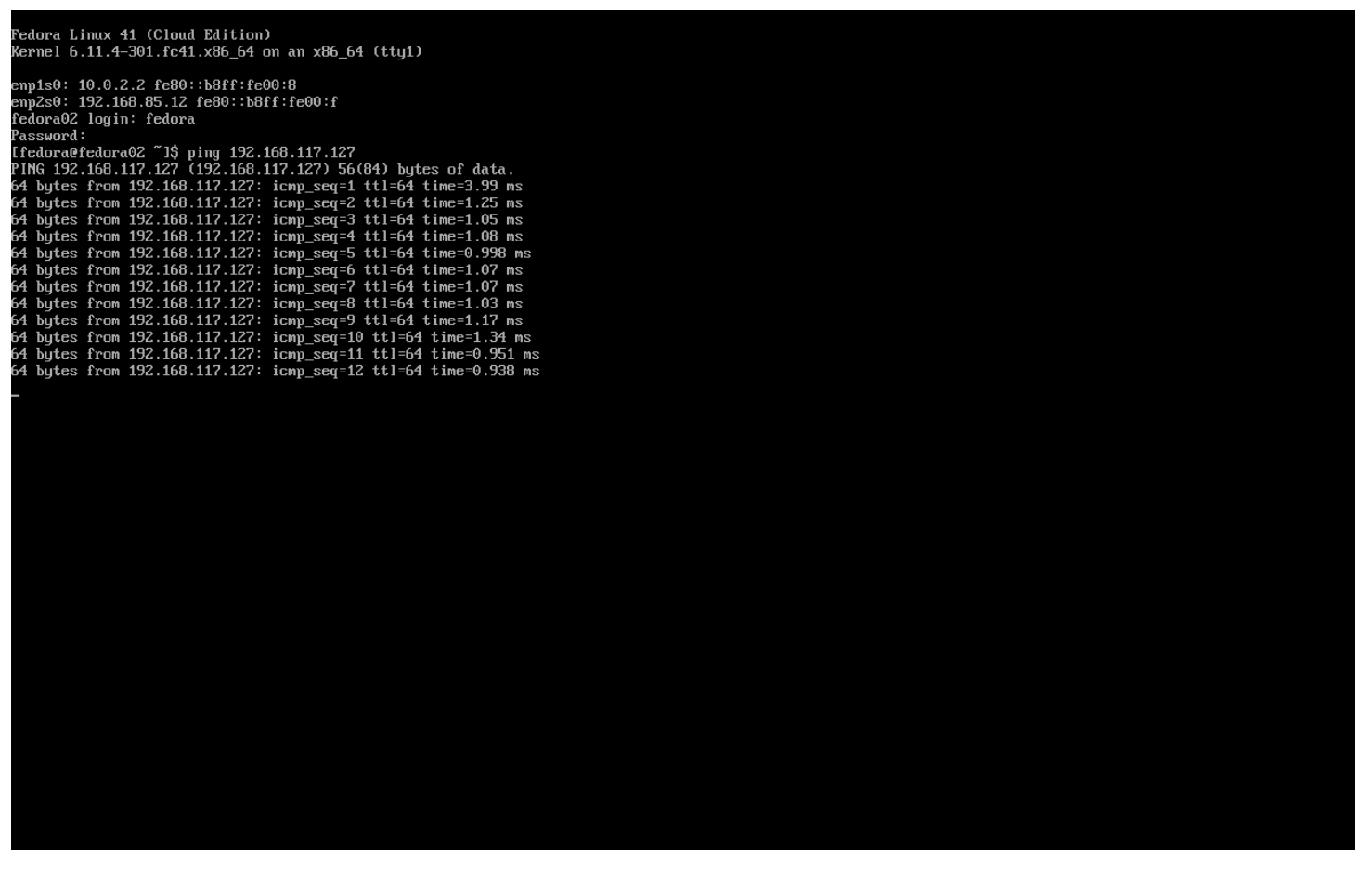
Use the Actions menu or the Play button to start the VM, and switch to the Console tab to watch it boot up.
The enp2s0 interface obtains an IP address from the flat network (192.168.64.0/18). That network has a DHCP server providing IPs to that network.
-
Repeat the actions to attach the fedora02 VM to the same flatnetwork network.
-
Use the ping command in the console to demonstrate direct communication between your two VMs (fedora01 and fedora02).
User Defined Networks
Before the implementation of user-defined networks (UDN), the OVN-Kubernetes CNI plugin for OpenShift Container Platform only supported a Layer 3 topology on the primary or main network. Due to Kubernetes design principles: all pods are attached to the main network, all pods communicate with each other by their IP addresses, and inter-pod traffic is restricted according to network policy. Learning a new network architecture is often an expressed point of concern from many traditional virtualization admins.
The introduction of UDN improves the flexibility and segmentation capabilities of the default Layer 3 topology for a Kubernetes pod network by enabling custom Layer 2, Layer 3, and localnet network segments, where all these segments are isolated by default. These segments act as either primary or secondary networks for container pods and virtual machines that use the default OVN-Kubernetes CNI plugin. UDNs enable a wide range of network architectures and topologies, enhancing network flexibility, security, and performance.
A cluster administrator can use a UDN to create and define additional networks that span multiple namespaces at the cluster level by leveraging the ClusterUserDefinedNetwork custom resource (CR). Additionally, a cluster administrator or a cluster user can use a UDN to define additional networks at the namespace level with the UserDefinedNetwork CR.
User-defined networks provide the following benefits:
Enhanced network isolation for security - Namespaces can have their own isolated primary network, similar to how tenants are isolated in Red Hat OpenStack Platform (RHOSP). This improves security by reducing the risk of cross-tenant traffic.
Network flexibility - Cluster administrators can configure primary networks as layer 2 or layer 3 network types. This provides the flexibility of a secondary network to the primary network.
Simplified network management - With user-defined networks, the need for complex network policies are eliminated because isolation can be achieved by grouping workloads in different networks.
Advanced capabilities - The user-defined networking feature allows administrators to connect multiple namespaces to a single network, or to create distinct networks for different sets of namespaces. Users can also specify and reuse IP subnets across different namespaces and clusters, providing a consistent networking environment.
User Defined Networks with OpenShift Virtualization
You can connect a virtual machine (VM) to a user-defined network (UDN) on the VM’s primary interface by using the OpenShift Container Platform web console or the CLI. The primary user-defined network replaces the default pod network in your specified namespace. Unlike the pod network, you can define the primary UDN per project, where each project can use its specific subnet and topology.
With the layer 2 topology, OVN-Kubernetes creates an overlay network between nodes. You can use this overlay network to connect VMs on different nodes without having to configure any additional physical networking infrastructure.
The layer 2 topology enables seamless migration of VMs without the need for Network Address Translation (NAT) because persistent IP addresses are preserved across cluster nodes during live migration.
You must consider the following limitations before implementing a primary UDN:
-
You cannot use the virtctl ssh command to configure SSH access to a VM.
-
You cannot use the oc port-forward command to forward ports to a VM.
-
You cannot use headless services to access a VM.
-
You cannot define readiness and liveness probes to configure VM health checks.
| OpenShift Virtualization currently does not support secondary user-defined networks. |
Working with User Defined Networks
You must create the namespace and network before creating pods that can access the UDN. Assigning a namespace with pods to a new network or creating a UDN in an existing namespace will not be accepted by OVN-Kubernetes.
This task has to be performed by a cluster administrator. You have assigned a namespace called vmexamples-{user}-udn with the proper label (k8s.ovn.org/primary-user-defined-network)
-
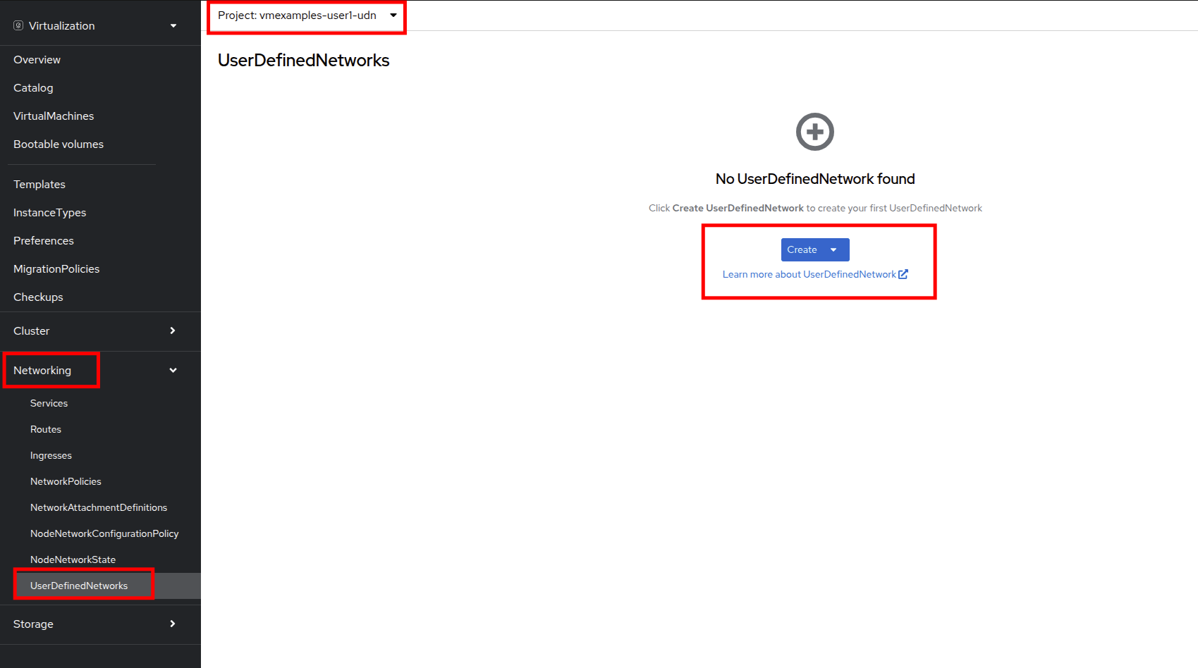
Navigate to Networking and then click on UserDefinedNetworks and ensure you select the project vmexamples-{user}-udn
-
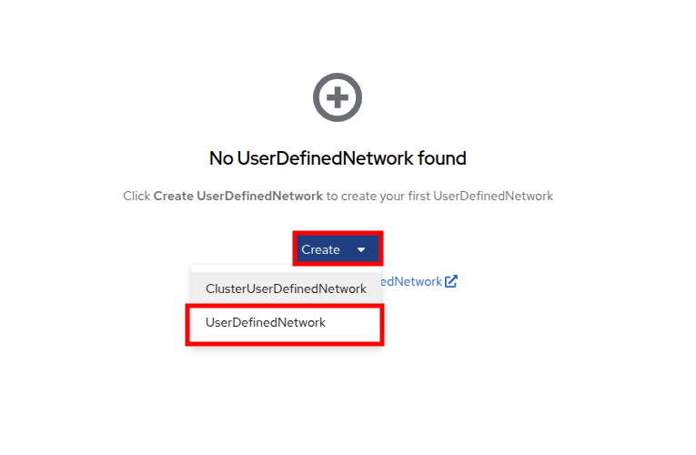
Click on Create and selet UserDefinedNetwork
-
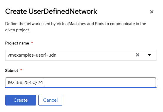
Specify the subnet 192.168.254.0/24 and press Create
-
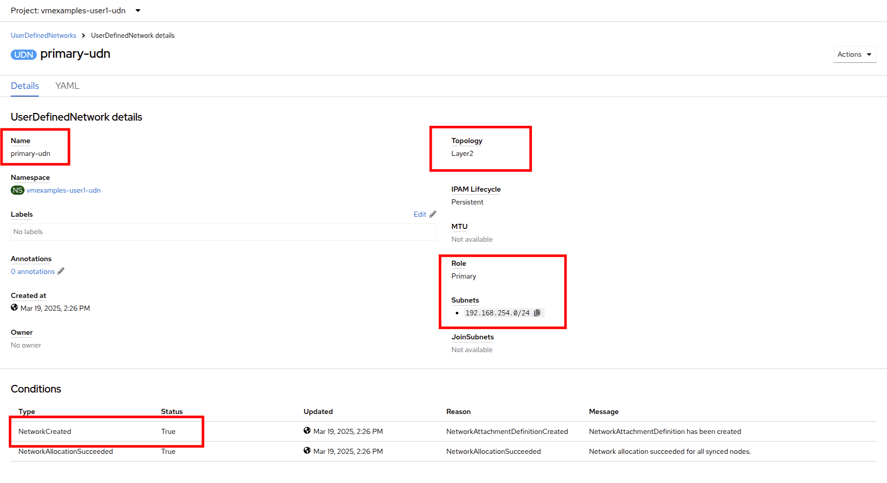
Review the configuration of the UDN just created
-
The Default name when it’s created using the form is primary-udn.
-
By default is Layer 2 (the only Layer supported at this moment for OpenShift Virtualization).
-
The Role is primary (Virtual Machines can only use, at this moment, primary networks).
-
A Network Attachment Definition is created automatically.
-
-
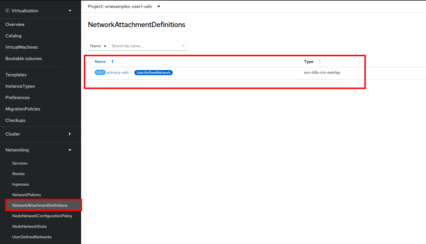
Now navigate to NetworkAttachmentDefinitions on the left-side menu and see that the associated NAD has been automatically created.
-
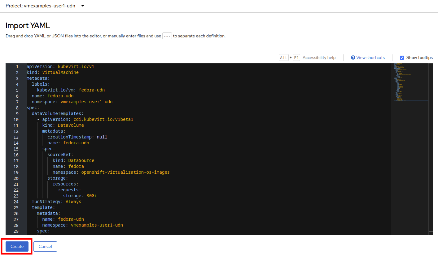
Creating a Virtual Machine attached to a UserDefinedNetwork requires some adjustment in the YAML definition. For this lab to make the task easier, we are just going to define the whole VM connected to the UserDefinedNetwork using the YAML definition below:
-
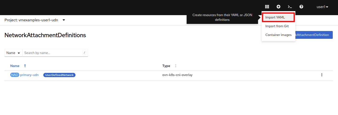
You can use the top menu to import a YAML as is shown in the following image:
apiVersion: kubevirt.io/v1 kind: VirtualMachine metadata: labels: kubevirt.io/vm: fedora-udn name: fedora-udn namespace: vmexamples-{user}-udn spec: dataVolumeTemplates: - apiVersion: cdi.kubevirt.io/v1beta1 kind: DataVolume metadata: creationTimestamp: null name: fedora-udn spec: sourceRef: kind: DataSource name: fedora namespace: openshift-virtualization-os-images storage: resources: requests: storage: 30Gi runStrategy: Always template: metadata: name: fedora-udn namespace: vmexamples-{user}-udn spec: domain: devices: disks: - disk: bus: virtio name: rootdisk - disk: bus: virtio name: cloudinitdisk interfaces: - name: primary-udn binding: name: l2bridge rng: {} resources: requests: memory: 2048M networks: - pod: {} name: primary-udn terminationGracePeriodSeconds: 0 volumes: - dataVolume: name: fedora-udn name: rootdisk - cloudInitNoCloud: userData: |- #cloud-config user: fedora password: fedora chpasswd: { expire: False } name: cloudinitdisk -
Once pasted in, you can click the blue Create button at the bottom to begin the VM creation process.
-
Switch to the VirtualMachines and watch at the VM is created. Once it is up and runing, review the newly created fedora-udn virtual machine. In the Overview tab, the Network tile will show the IP assigned from the UserDefinedNetwork.
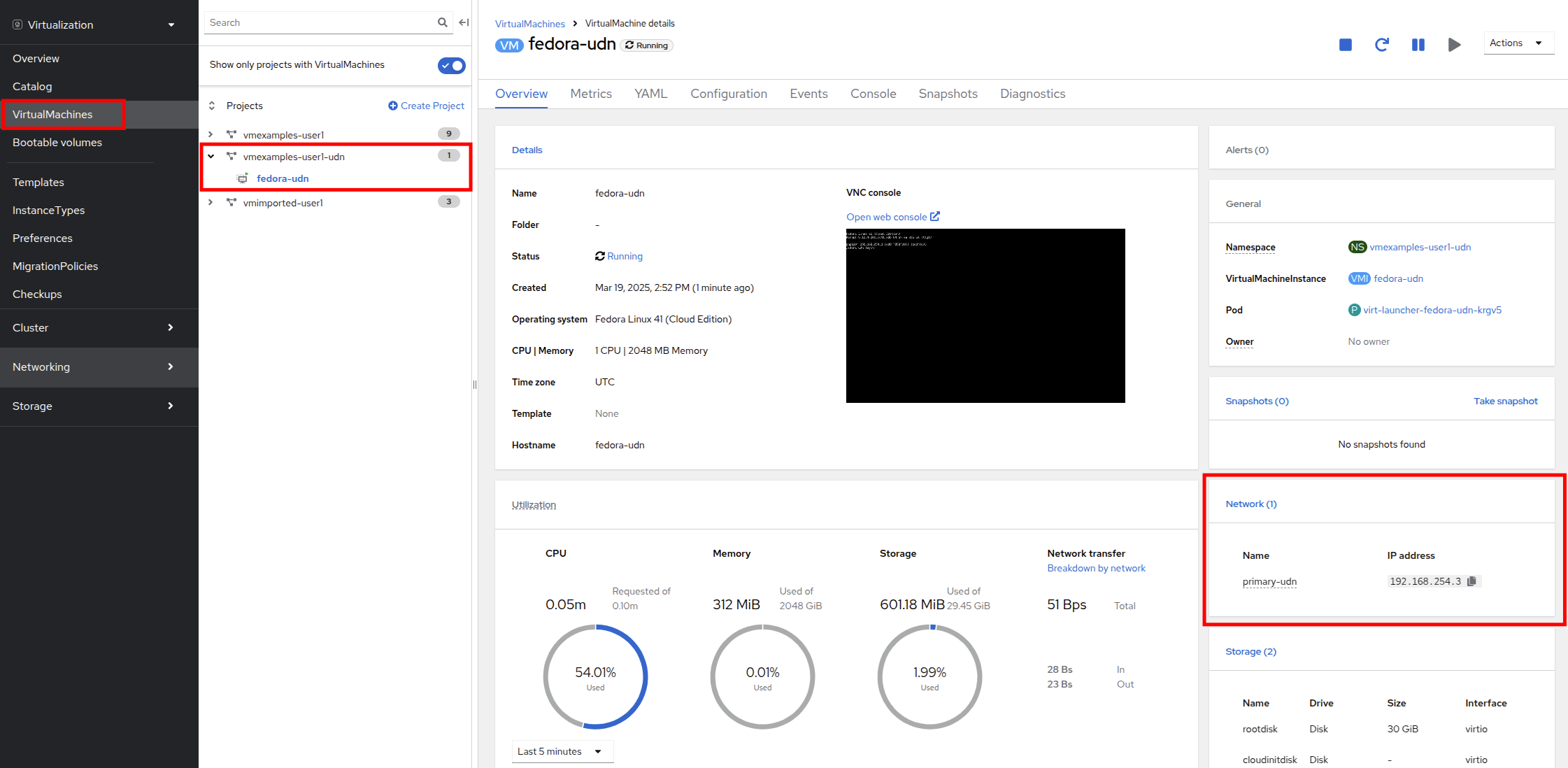
-
Switch to the Console tab and login to the VM using the provided guest credentials.
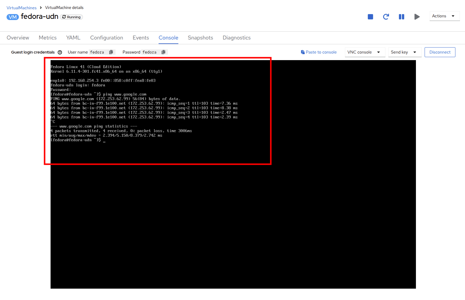
-
The VM has assigned a IP from the subnet defined
-
The VM automatically gets the gateway configuration from a DHCP
-
The VM has access to internet using the User Defined Network.
-
Summary
In this module, you explored working with physical networks and connecting Virtual Machines (VMs) directly to an existing network. By attaching VMs directly to a physical network administrators can directly access the VMs while also enabling the VMs to connect to specialized networks, such as storage or administration networks.
User-defined networks provide cluster administrators and end users with highly customizable network configuration options and a much more flexible experience for managing both primary and secondary network types.